
On a soil nail wall built top down, two numbers decide whether the face stands: how high each lift is cut, and how long it stays open before it is supported. This case study follows a package that went to market on assumptions about both numbers. The assumptions turned out to be incorrect, and the package had to go back to market. By the end you will know why the gap opens, what the published guidance says about it, and how a site or project engineer can settle lift height and stand up time with the geotechnical designer before the package is priced.
The work pack
The case comes from the engineer who built TworkX, writing a work pack for a soil nailing package on a major Australian project. The project is not named.
The method was top down. Cut a lift, expose the face, support it, install the nails, apply the facing, then cut the next lift. That sequence is standard. What made this pack different was where its key numbers came from.
The package went to market with assumptions about the height of each lift and how long each cut face would stand open. Prospective subcontractors priced the work on those assumptions, and they became the method the work pack had to describe.
Writing the work pack showed that those assumptions were incorrect. Two things did not line up.
- On another scope of the same project, the geotechnical advice for the same activity limited each lift to half that height, and limited how long a cut face could be left exposed.
- In this scope, the design made no allowance for the excavated face to stand open while the nails and facing went in.
So the package on the street assumed a lift twice as high as the ground elsewhere on the project was allowed to stand, and an open time the design had never considered.
How it was resolved
The engineering problem was solved at the work pack stage. The engineer developed a new cadence for cutting and supporting the face, so the work could be built the way the ground allowed.
The commercial problem could not be solved the same way. The package had gone to market on lift height and exposure assumptions that turned out to be incorrect: the work could not be built that way. The tender process was restarted. There was no variation, because the problem was caught before the subcontract was signed. Had it been signed on those inputs, the gap between what was priced and what the ground allowed would have cost the project a significant amount of money.
The face could not be built the way the package assumed. Halving the lift height doubles the number of lifts to reach the same depth, and every extra lift repeats the full cycle of cut, inspect, support, nail and face. A cadence built around a short open time can also change the crew, the plant and the shifts. None of that had been priced.
Why this happens on so many jobs
Nobody on this job did anything wrong. Each party worked from the information in front of them. The problem is structural, and it shows up wherever ground work is priced before the ground questions are asked.
Ground information is written for the designer
Ground information reaches site as a geotechnical report, borehole logs and interpretive advice written for the permanent design. It is thorough, but it answers the designer's questions. The site engineer reads it through a narrow window: a groundwater level, a soil description, perhaps a strength value. What it rarely answers directly is how high a face can be cut and how long it can stand while it is being built.
The critical step is temporary
The US Federal Highway Administration's soil nail wall manual (GEC 7, an overseas source widely read here) describes the excavation of each lift as the step where the face "must have the ability to remain unsupported" until the nails and initial facing are in. The California transport department's soil nail guidance makes the same point and lists the problems that follow when a face stands too long: dry sandy faces sloughing, and drying, weathering and instability from prolonged exposure after excavation.
Research on cuts in sand above the water table explains why such faces can stand at all. Stanier and Tarantino (2013) showed that suction in the partly saturated sand adds strength that classical soil mechanics ignores. That strength is real, but it belongs to the ground's moisture state on the day, not to the design.
Time open is a hazard in its own right
Safe Work Australia's model Code of Practice for excavation work lists how long an excavation is open as a factor in its risk. It notes that sandy soils can lose cohesion as they dry, that a face that looks sound can crumble with small changes in moisture, and that ground left idle should be checked before work restarts. A face cut at the end of a Friday shift and supported on Monday has stood open through the whole weekend. On paper the sequence is the same. In the ground it is not.
The specifications control it through sequence, not a number
The Australian road specifications for soil nailing control the risk through the construction sequence. Austroads ATS 5130 requires the face to be left unsupported for as short a time as possible, an inspection of each lift by an engineer, measures to protect the face where nails go in before the shotcrete, and a minimum wait before the next lift. Transport for NSW R64 limits each lift and how far it may go below the nail row being installed, and requires an inspection of the exposed face after each lift. The Victorian Section 683 has the sprayed concrete applied to the face before the nails are drilled, and sends any ground that differs from the design back to the designers.
None of these documents can tell you the stand up time of your ground. That comes from the geotechnical designer, for the ground and the method on your job. If nobody asks, the package goes to market on an assumption.
What would have prevented it
The fix is not more site investigation. The ground information was always there. What was missing was a way for the construction engineer to turn the planned method into questions the geotechnical designer could answer, before the package went out.
TworkX is built for that step. Using only the project's existing geotechnical information, the engineer describes the dig and the method as data. TworkX lays out what follows from those entries and flags what the designer still has to confirm.
| What went wrong | What the engineer sees in TworkX before tender |
|---|---|
| Lift height assumed when the package went out | Each lift drawn on the final section, numbered, with its level and the ground it stands in, from the crest down to the base |
| Open time never stated | The cadence of each lift: the steps from the cut to the step that first supports the face, with their hours and the shift pattern, and the open time worked out from them |
| A face open over nights and weekends | The open time is worked for the worst case, a cut finishing at the end of a shift and of the working week, and a lift standing open through a night or a day off is flagged |
| Open time longer than the ground allows | A Major item where the open time is longer than the stand up time entered from the geotechnical advice, which stays open on the brief until it is resolved |
| Ground the face cannot rely on | Advisory flags where a layer in the face records no effective cohesion, where fill is in the face, where a layer boundary falls inside a lift, or where groundwater stands above the base of the face |
| Specification sequence missed | The lift height and hold the engineer takes from the project specification are compared with the cadence, and a cadence with no face inspection is flagged |
The engineer enters the stand up time and the specification values from their own documents. TworkX supplies none of them. It compares the method with what the engineer has entered and says where they disagree.
The result goes to the geotechnical designer as a lift schedule in the design brief: each lift, the cadence, the open time, the stand up time entered and the ground flags, with the A3 support detail showing where each question applies. The designer receives a sequence they can check quickly, not an assumption to unpick after the package has gone out.
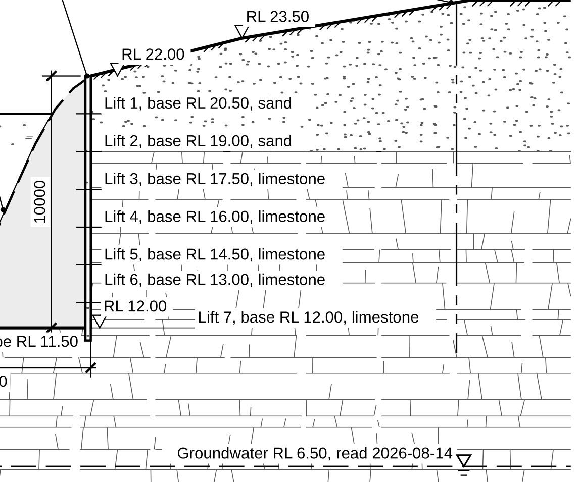
An invented worked example, the Example widening cut. Each lift is numbered with its level and material, so the lift height can be read against the ground before anyone prices it.
For the engineer who wants a feel for the margin, the advisory ground stability checks sit beside the brief. They include hand calculations such as the critical height of a vertical cut, and finite element analysis that follows the dig stage by stage. These results are marked Advisory, Indicative and Beta, and never replace the design.
The same job, done in this order
- Enter the ground from the geotechnical report, and draw the dig as a face built top down.
- Enter the cadence the method needs, and see the open time of each lift, including nights and days off.
- Send the lift schedule to the geotechnical designer with the questions it raises: the lift height and the longest open time for each layer, and the hold point between lifts.
- Put the confirmed lift height, cadence and hold into the tender documents, so every subcontractor prices the same buildable method.
Done in that order, the lift height in the tender matches the ground, the open time has been asked about, and the right cadence is priced in the first tender.
What it means for the site engineer
The construction engineer runs the excavation and often holds the thinnest understanding of the ground being cut. That is not a criticism. The information they receive is written for someone else. The answer is to give them a way to work with it: to see the method against the ground, ask the designer precise questions, and meet the designer where they are.
If you are about to price or plan a soil nail wall, see how TworkX works and the sample brief.
Sources
- US Federal Highway Administration, Soil Nail Walls Reference Manual, GEC 7, FHWA-NHI-14-007, February 2015
- California Department of Transportation, Geotechnical Manual, Soil Nail Walls, January 2026
- Stanier and Tarantino, An approach for predicting the stability of vertical cuts in cohesionless soils above the water table, Engineering Geology, 2013 (author's proof)
- Safe Work Australia, Model Code of Practice: Excavation work, October 2018, sections 2.2, 6.1 and 6.7
- WorkSafe WA, Excavation: Code of practice, updated 25 November 2024
- Austroads, ATS 5130 Soil Nails, Edition 1.0, January 2025, clause 7
- Transport for NSW, R64 Soil Nailing, Edition 1 Revision 8, December 2025, clause 3.3
- Department of Transport Victoria, Section 683 Soil Nail Walls, April 2019, clause 683.05