
3D modelling for temporary works is the practice of describing an excavation, a formwork pour or a scaffold as a model of the site rather than only as words and sketches. On site its main use is communication: showing the designer, the site team and the people around the works exactly where the ground, the services, the neighbours and the stages sit before anyone designs or builds. A model does not design anything, and it is not a substitute for the temporary works design. By the end of this article you will know what a temporary works model is good for, which open file formats let it travel between programs, what it should carry for the designer, and where its limits are.
Why model temporary works at all
Most of what goes wrong with a temporary works design starts with missing or unclear information: a service that was not shown, a footing closer than the brief said, a stage that was never described. A 3D model helps because it makes those gaps visible. When the ground, the excavation and its surroundings are drawn together, a missing level or an impossible stage tends to stand out in a way a list of answers does not.
There are three practical uses on an Australian site.
- Coordination. Put the temporary works beside the permanent works, the services and the adjacent structures, and check they fit. A strut through a future column or a scaffold standard over a live sewer shows up on screen before it shows up on site.
- Staging. Temporary works change from stage to stage. A model that steps through the stages shows what is dug, propped or removed at each one, which is exactly what a designer has to know.
- Briefing. A model gives the designer the same picture the site team has, with the levels and set out attached, so the design starts from the site as it is.
In the United Kingdom, The Structural Engineer has argued that temporary works should be brought into a project's digital process from the start rather than late in delivery, because that is where the benefit is greatest. Australian projects can draw the same lesson, while following Australian regulations and their own project requirements.
What the regulations already ask for
A model does not create new duties, but it is a good way to meet existing ones. Safe Work Australia's model Code of Practice for excavation work expects the person with management or control of the workplace to take all reasonable steps to obtain current information about underground essential services in and around the excavation before work starts, and to pass it on to the principal contractor and the excavation contractor. The code also covers preventing the collapse of adjacent buildings and structures. Safe Work Australia published a new edition of the model code in November 2026. Each state and territory adopts the model code with its own changes, so check the version that applies where you work.
Those are the same things a model of an excavation shows: where each service runs and at what level, where the neighbours' footings are, and how the dig relates to them. Recording them once in a model, with their source, means the designer, the site team and the regulator all see the same information.
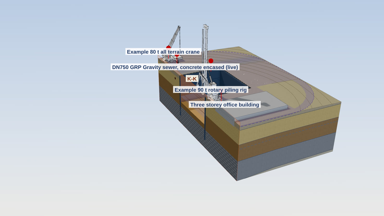
Illustration of an invented worked example: a basement in a piled wall beside a sewer, cut across its middle. Not a design.
Open formats: IFC, BCF and glTF
A model is only useful if it opens in the program the other person uses. Three open formats cover most temporary works needs.
| Format | What it is for | Who maintains it |
|---|---|---|
| IFC (Industry Foundation Classes) | Exchanging building and infrastructure models between BIM programs, with each element's properties | buildingSMART International, published as ISO 16739 |
| BCF (BIM Collaboration Format) | Raising issues about a model, each tied to the elements it concerns, and passing them back and forth | buildingSMART International |
| glTF | Viewing a 3D scene quickly in almost any 3D program or on a phone | The Khronos Group, published as ISO/IEC 12113 |
IFC is the format for the designer and the BIM team. It is an open, vendor neutral schema, maintained by buildingSMART International, and IFC 4.3, which extends it to roads, rail and other infrastructure, was published by ISO as the latest edition of ISO 16739 in 2024. An IFC file carries each element with its properties, so a temporary works element can say what it is, where its information came from and that it is indicative.
BCF carries the conversation about the model. Each issue points at the elements it concerns by their IFC identifiers and carries a viewpoint, so a designer's question about one strut comes back pointing at that strut.
glTF is for looking, not for designing. The Khronos Group describes it as a royalty free format for delivering 3D scenes and models efficiently, and it was published as ISO/IEC 12113 in 2022. It is the easiest way to show a stage of the works to a foreman, a client or a neighbour on a phone.
Some Australian projects also run under a client's digital engineering requirements. Transport for NSW, for example, publishes a Digital Engineering Framework covering how models and data are planned, coordinated and handed over. Where a project has requirements like these, ask the digital engineering manager how temporary works models should be named, structured and shared before you send one.
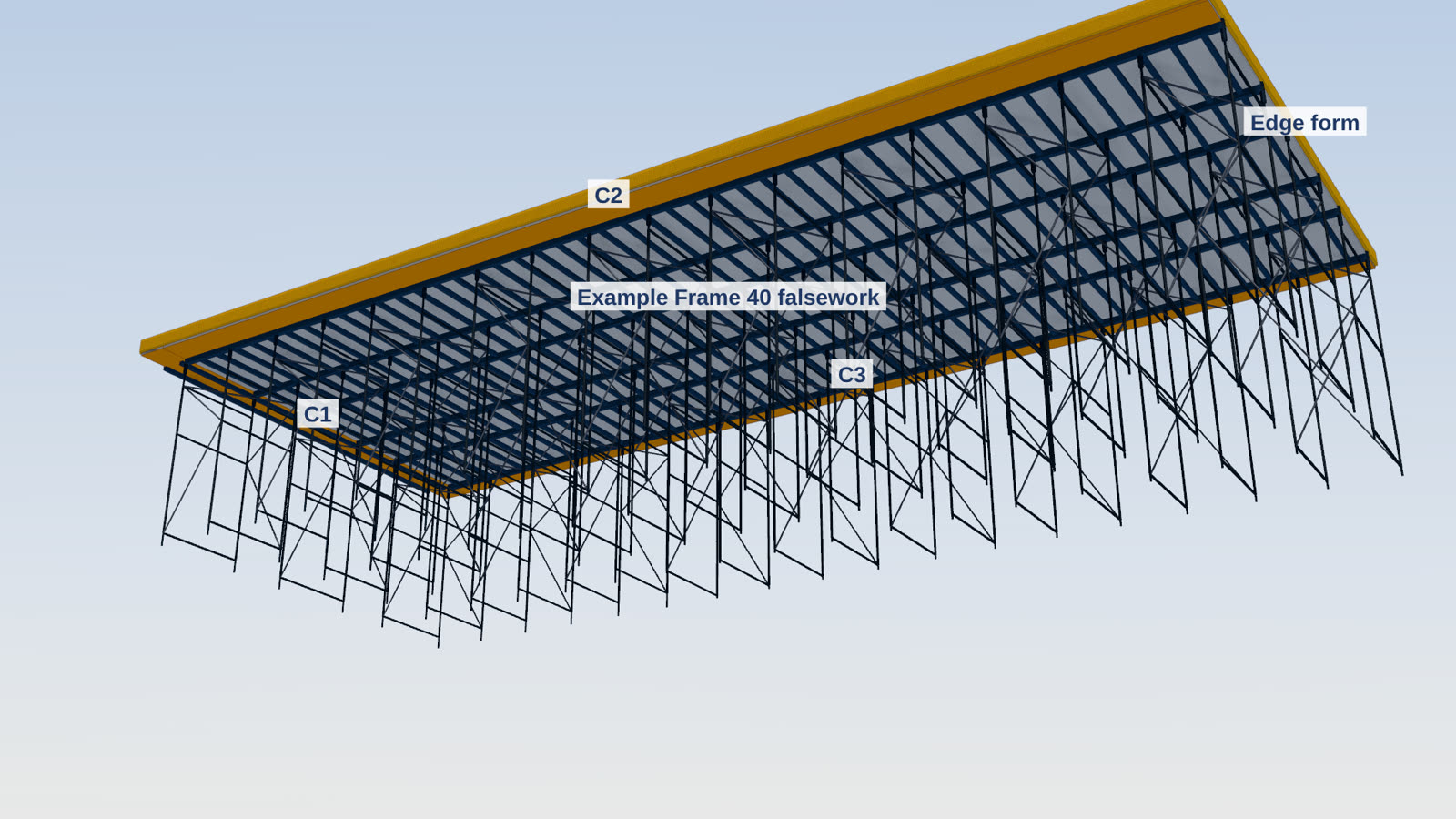
Illustration of an invented worked example: a slab on frame towers. Members are indicative and their sizes are for the designer. Not a design.
What a temporary works model should carry
A model for the designer is a briefing document in 3D. It should carry what the designer needs and say where each piece came from.
| In the model | What to record with it |
|---|---|
| The existing ground and its layers | The survey or the boreholes it comes from, and that strata between boreholes are interpolated |
| Groundwater | The level, the date it was read and the source |
| Each service | Its type, size, level and how its position was found (records, potholing, location survey), and the owner's requirements |
| Adjacent structures | Their outline, founding level where known, and the source |
| Plant and surcharges | What stands where, at each stage, from the method statement |
| The excavation or the works | Each stage, with what it digs, places or removes |
| Support or falsework | Shown as indicative, with no member sizes |
| Levels and set out | Reduced levels on the project datum, and the coordinate system the set out uses |
Two habits make a model far more useful. First, keep every level as a reduced level on the project datum, and say which datum. Second, keep the set out on the project's coordinates, so the model lands in the right place when the designer loads it beside the permanent works.
The limits of a model
A model is a picture of the information, not a design and not a check of one.
- Indicative is indicative. Support, props, struts and scaffold members drawn in a briefing model are there to show the arrangement. Their sizes, spacings and capacities are the designer's.
- The model is only as good as its sources. An interpolated ground model between boreholes is a guess between the holes. Say so in the model, and send the geotechnical report with it.
- The drawings and the brief stay the record. Use the model to communicate, and keep the issued brief and drawings as the documents of record.
- Mind the exaggeration. Many viewers stretch levels to make thin layers visible. Export at true scale, and say so.
A short checklist before you send a model
- Every element says what it is, where its information came from, and that it is indicative.
- Levels are reduced levels in a stated datum; the set out is on the project's coordinates.
- Services carry how their position was found.
- Stages are named, and each stage shows what changes.
- No member sizes, loads or capacities are in the model.
- The file opens in a free IFC viewer before it goes out.
- The designer has the brief and the drawings with it.
TworkX draws this kind of model from the brief data and exports it as IFC and glTF; see the modules and the capabilities page, and the products page for the rest of what TworkX does on site. The design stays with the temporary works designer.
Sources
- buildingSMART International, IFC 4.3 documentation: introduction
- buildingSMART International, newsletter, April 2024: IFC 4.3 published as an ISO standard
- buildingSMART International, BIM Collaboration Format (BCF)
- The Khronos Group, glTF: runtime 3D asset delivery
- Engineering.com, Khronos glTF 2.0 released as an ISO/IEC international standard, August 2022
- Safe Work Australia, Model Code of Practice: Excavation work, November 2026
- Transport for NSW, Digital Engineering Framework
- The Structural Engineer (UK), Aligning temporary works with the Digital Plan of Work, volume 99, issue 1, 2021